Howdy, Stranger!
It looks like you're new here. If you want to get involved, click one of these buttons!
Categories
- 920 All Categories
- 3 Picture Posting and Resizing
- 53 New Member Introductions
- 111 Off-Topic Forum
- 4 Photography
- 2 Resources
- 16 New Product Information
- 165 The SierraWest Forum
- 9 Brett's Blog
- 117 General News & Ramblings
- 3 Re-Release Information
- 6 Q & A about SierraWest
- 9 What Would You Like to See?
- 361 Builds
- 131 HO Scale Builds
- 154 O Scale Builds
- 59 Finished SW Build Pics
- 12 Miscellaneous Builds
- 187 Techniques
- 19 Working with Wood
- 20 Painting Castings
- 5 Masonry
- 23 Scenery
- 36 Tools and Supplies
- 21 Layout Planning & Building
- 38 Miscellaneous
- 24 Prototype Information
- 22 Reference and Research
Layout Planning for SWSM
I hope everyone that made it to Narrow Gauge Convention is having a great time. I spoke with Brett a while back and he suggested this might be of interest to those thinking of building a layout, or those who engage in armchair railroading.
I became aware of Brett's models about the time I started designing my layout and it just naturally followed to incorporate them into the design. What I've discovered is an iterative process that helped me arrive at a point that I would have fought and had to have reworked to arrive at.
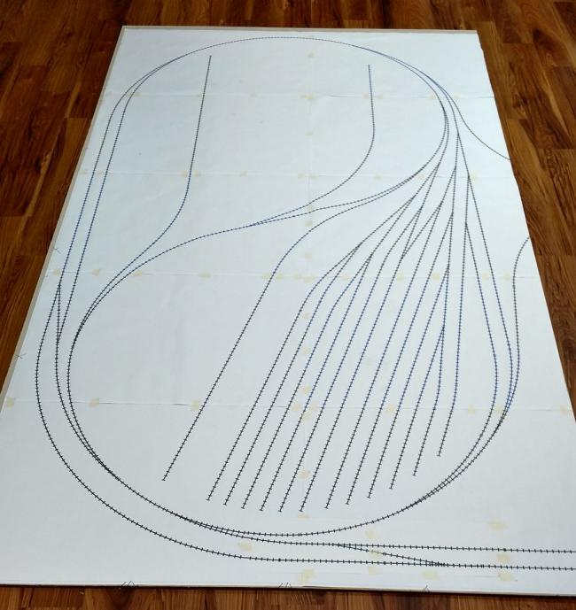
Taking a cue from the building threads here, I realized the first step to success was to plan. I used a computer program to develop the layout. I then printed out the layout full size on 2'x3' sheets 1:1 so it could be transferred to the layout as can be seen in the following photo.
The setting of the layout is Laramie, Wyoming in the mid 1930's. The main setting of this portion of the layout is the main yard in Laramie Wyoming that interfaces with a branch line, the Laramie, North Park, and Western RR. One of the things I wanted to accomplish was building the layout in such a way that all structure modules would be removable to be able to be integrated into the layout, yet able to be removed and saved if I ever decided to dismantle the layout. The other key factor was that I wanted this portion of the layout to tell a cohesive story set in the West Laramie area incorporating layout, locomotives and rolling stock, as well as terrain, and structures.
Keeping that in mind helped select the models I wanted to incorporate into the scene. I was confident that I wanted to have O'Neill's Fabrication and J. E. Morton's together on one siding. I had picked up Duluth Plumbing and the Freight House and felt they would make a good pairing. I had picked up an FSM kit that felt like it would add good variety. I had picked up a scrap yard kit, but had some serious reservations about the quality, plus Quincy's Salvage had been out of production for a while and was not that common. I was able to pick up Quincy's on the third party market.
QUINCY'S SALVAGE
Quincy's started to take on a huge impact on the layout as the spur that serves it, is at a lower elevation. I feel comfortable with Brett's plan, so the challenge I had, was how to fit in the module with an appropriate slope down to the elevation of the spur as it actually related to the rest of the layout. That sounds easy, but matching the height of the trestle on Quincy's to the height of the grade entering the module presented a challenge. It turns out that normal ties are a scale 7" thick, while bridge ties are 8" thick. In addition I wanted to create the module so that it was removable, which meant that I needed to figure out how to make the approach track separable.
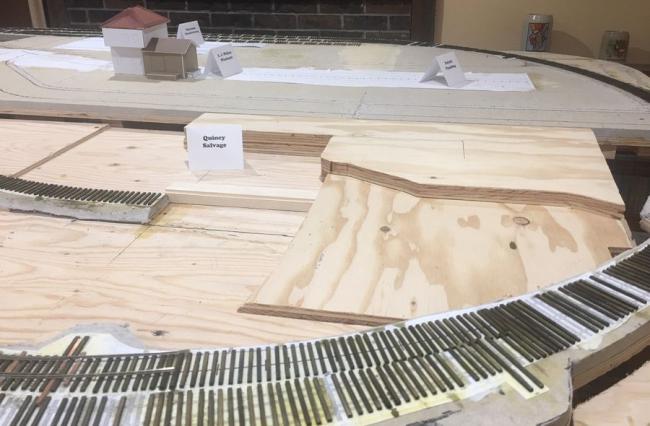
Here are a couple of pictures of the Quincy area of the layout as I was figuring out the approach elevation.
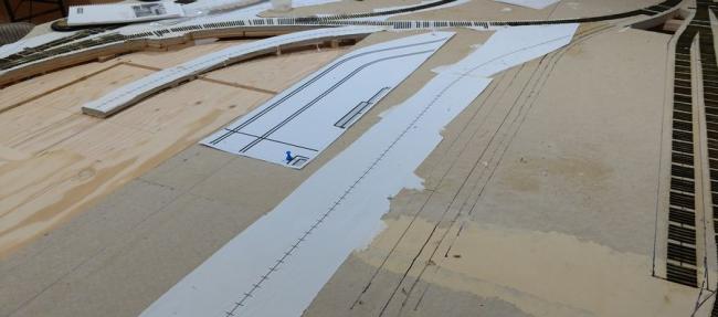
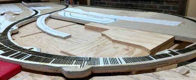
The challenge was that I needed the transition from the switch into the spur as well as the lead to Quincy's being level to yield reliable operation. The lead in spur was about 30 inches. The drop in elevation from the spur entrance to Quincy's to the trestle elevation was 0.88". I planned the grade transitions by dividing the spur into five segments of 5.5" each. This yielded a grade of about 5% which is acceptable as it is a relatively short distance. I cut out a strip of wood to the same dimensions as the trestle to help me visualize how I need to fit in the trestle. (Note the split in the roadbed at the break in the structure module.)
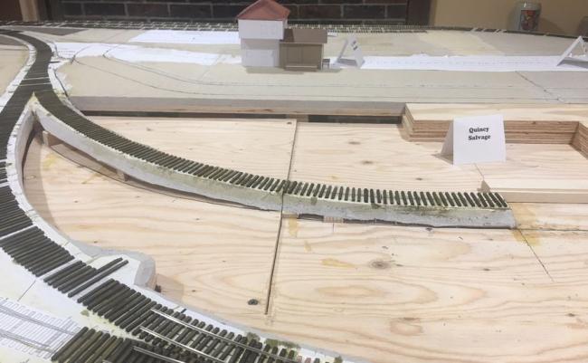
This photo shows the layers of the Quincy module pretty much as laid out in Brett's construction manual. I lengthened them to the right to make it easier to transition to the surrounding terrain.
The next step on Quincy's will be looking at what the terrain will look like transitioning to the adjoining area to know how the terrain on the Quincy module will need to be shaped.
SEPARATING THE MODULES
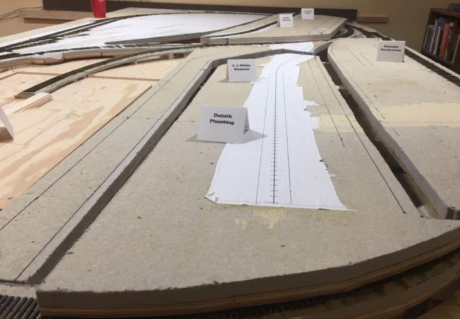
Before I moved further, I cut out the modules for each of the structure areas. I tried to align these so that the seams between the sections would be able to hidden with either scenery, roadways, or trackwork.
O'NEILL'S AND J E MORTON
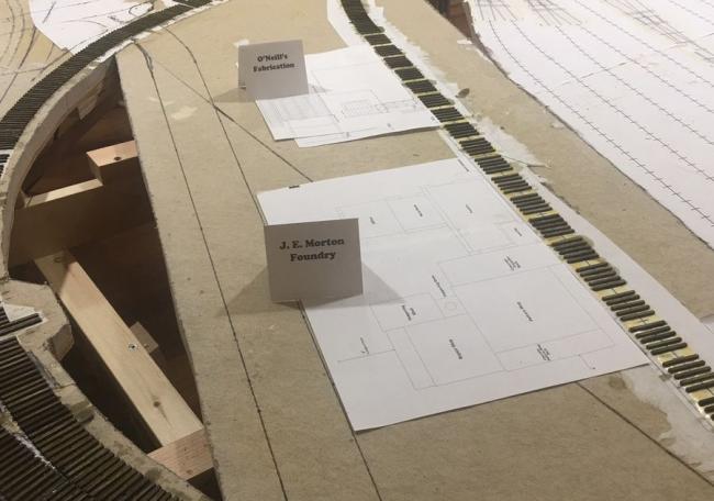
I started the design shortly after O'Neill's was released. It wasn't long afterwards that he mentioned the prospect of J E Morton's coming in the future. I used the templates provided in the kits to lay out the placement of the two kits.
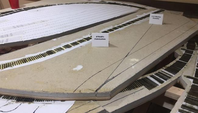
Per the NMRA standard for HO, the distance from track centerline to loading platforms or docks. I drew a line parallel to the rail lines and positioned the templates accordingly.
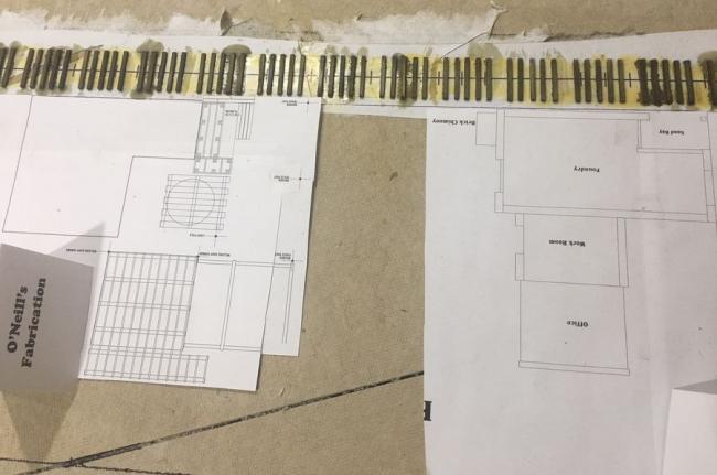
Checking the alignment and relationship with the planned gravel road.
To be continued...
Mark
I became aware of Brett's models about the time I started designing my layout and it just naturally followed to incorporate them into the design. What I've discovered is an iterative process that helped me arrive at a point that I would have fought and had to have reworked to arrive at.
Taking a cue from the building threads here, I realized the first step to success was to plan. I used a computer program to develop the layout. I then printed out the layout full size on 2'x3' sheets 1:1 so it could be transferred to the layout as can be seen in the following photo.

The setting of the layout is Laramie, Wyoming in the mid 1930's. The main setting of this portion of the layout is the main yard in Laramie Wyoming that interfaces with a branch line, the Laramie, North Park, and Western RR. One of the things I wanted to accomplish was building the layout in such a way that all structure modules would be removable to be able to be integrated into the layout, yet able to be removed and saved if I ever decided to dismantle the layout. The other key factor was that I wanted this portion of the layout to tell a cohesive story set in the West Laramie area incorporating layout, locomotives and rolling stock, as well as terrain, and structures.
Keeping that in mind helped select the models I wanted to incorporate into the scene. I was confident that I wanted to have O'Neill's Fabrication and J. E. Morton's together on one siding. I had picked up Duluth Plumbing and the Freight House and felt they would make a good pairing. I had picked up an FSM kit that felt like it would add good variety. I had picked up a scrap yard kit, but had some serious reservations about the quality, plus Quincy's Salvage had been out of production for a while and was not that common. I was able to pick up Quincy's on the third party market.
QUINCY'S SALVAGE
Quincy's started to take on a huge impact on the layout as the spur that serves it, is at a lower elevation. I feel comfortable with Brett's plan, so the challenge I had, was how to fit in the module with an appropriate slope down to the elevation of the spur as it actually related to the rest of the layout. That sounds easy, but matching the height of the trestle on Quincy's to the height of the grade entering the module presented a challenge. It turns out that normal ties are a scale 7" thick, while bridge ties are 8" thick. In addition I wanted to create the module so that it was removable, which meant that I needed to figure out how to make the approach track separable.
Here are a couple of pictures of the Quincy area of the layout as I was figuring out the approach elevation.


The challenge was that I needed the transition from the switch into the spur as well as the lead to Quincy's being level to yield reliable operation. The lead in spur was about 30 inches. The drop in elevation from the spur entrance to Quincy's to the trestle elevation was 0.88". I planned the grade transitions by dividing the spur into five segments of 5.5" each. This yielded a grade of about 5% which is acceptable as it is a relatively short distance. I cut out a strip of wood to the same dimensions as the trestle to help me visualize how I need to fit in the trestle. (Note the split in the roadbed at the break in the structure module.)
This photo shows the layers of the Quincy module pretty much as laid out in Brett's construction manual. I lengthened them to the right to make it easier to transition to the surrounding terrain.
The next step on Quincy's will be looking at what the terrain will look like transitioning to the adjoining area to know how the terrain on the Quincy module will need to be shaped.
SEPARATING THE MODULES
Before I moved further, I cut out the modules for each of the structure areas. I tried to align these so that the seams between the sections would be able to hidden with either scenery, roadways, or trackwork.
O'NEILL'S AND J E MORTON
I started the design shortly after O'Neill's was released. It wasn't long afterwards that he mentioned the prospect of J E Morton's coming in the future. I used the templates provided in the kits to lay out the placement of the two kits.
Per the NMRA standard for HO, the distance from track centerline to loading platforms or docks. I drew a line parallel to the rail lines and positioned the templates accordingly.
Checking the alignment and relationship with the planned gravel road.
To be continued...
Mark


Comments
DULUTH PLUMBING, FREIGHT HOUSE, AND E. J. WHILEY'S
This area really proved to be a bit of a challenge for me and is where the real iterative look at it made a difference. My initial plans called for Duluth Pluming, and the Freight House located where E J Whiley's ended up. As luck would have it, I looked at Whiley's and really liked the lines and layout, plus the stone office tied in well with Morton's.
I was satisfied with the location of the road relative to Quincy's although it is slightly different than Brett's plans. I was satisfied with the road/siding relationship for Duluth and the Freight house originally as shown in this photo.
Here is where I get to give a shout-out to Joel Freedman. He had an E. J. Whiley's kit he was willing to part with and was a real joy to do business with. When I had a chance to look over the kit, it had a larger footprint than the Freight House did. I decided to build a mock up of it to get a better idea of its spacial orientation.
When I did this, I realized that there really was not enough room to park a truck in front of the loading dock on the brick building, so opted to redesign the layout to leave an adequate space where a truck could be backed into the loading dock.
Using the same technique of drawing the line 13/16" away from the track centerline, I realized that I needed to shift the siding over 3 inches to allow for the room for the truck.
This in turn necessitated revisiting the roads and finalizing the "right of way" for the asphalt roadway with gravel road extensions to all the industries including across the track to O'Neill's and Morton's.
The last thing to do was to tie down the individual structure modules to the layout to ensure the alignment of trackwork and all elements was secured.
Now work can proceed with trackwork, and I can comfortably remove a structure module to be worked on at the work bench comfortable that the elements will fit and all the trackwork is aligned both horizontally and vertically.
Thanks for reading this far. I hope this helps someone along the way.
Mark
Mark
Terry
George
I'm an engineer by trade and so can be a bit picky about some of the details. As I've read some of the build threads, it is apparent that most take a good deal of time to figure out composition of the diorama. In this case, in essence I'm building one large diorama of an industrial area with an operating layout in the midst of it.
The other unspoken reason I'm approaching just this area first, is that I now have three grandkids, three and under, that I am hoping will want to learn to run Grandpa's trains. So it turns out to be a legacy project. If I get the layout running, I can then take out a module and build in the Sierra West element while the grandkids can run trains.
Mark
This is an updated photo of the section for Quincy's Salvage. I've added general terrain. I've designed this as a module. You can see the dividing point at the pink foam and homosote. This will allow me to build the entire Quincy module at the workbench then install it on the layout.
This photo shows a grouping of straight and curved turnouts.
Here is the straight mainline tracks continuing from the turnouts in the photo above.
This curved turnout ties in to the mainline straight mainline tracks above.
All the track work is built using tools and fixtures from FastTracks. There is really good documentation on their website that shows how to construct turnouts using their fixtures. What I've found missing are guides for installing, weathering, and wiring the track to match the handlaid ties.
I know a lot of people do such amazing work on dioramas, so I'm just wondering if anyone really would like for me to post information on how I wire, weather and install the turnouts and track. So if you are interested, would you please let me know in comments below.
Thanks as always,
Mark
Terry
My experience with layouts in the past showed me that trackwork is the most critical aspect of operating a model railroad. If you have one place where you are going to have derailments, your level of satisfaction in the whole layout drops, so for me, operational reliability is key. I use full 3' lengths of code 70 rail for this part of the layout. I have looked at the splice plates that are available and will add them at the structure detail sections.
The room in which I have my layout is in our basement, and does not suffer any great temperature or humidity changes. We have a humidifier installed in our heating / a/c system, so our humidity stays relatively uniform also. I typically solder the rail joiners on the track at critical electrical joints where track may be in a shorter section such as splicing into a turnout lead. I do solder a feeder wire to each 3' section of track, so there is no section of track that is dependent on a rail joiner for electrical power feed through.
The different sections of my layout represent different rail lines. This part represents the Union Pacific Yards in West Laramie and so I wanted the track to appear to be fairly well maintained. I used a stain for these ties that I found in a Lex Parker video on building a trestle. It uses alcohol, black shoe dye, and a touch of brown shoe dye for warmth. I prestained the ties before laying them down. Once in place, I lightly sanded the alignment with a sanding block to ensure all the ties were level, then came back with a brush and touched up the top surface, which is where some of the natural variation comes from.
In using the method I do for creating the turnouts and long straight sections, you will have PC board (copper clad) ties spaced throughout the section. I prime each of these with a gray primer before installing, then touch up the upper surface afterwards. I then go in and 'stain' these painted ties with the original stain used on the wood, and they become virtually indistinguishable from the wood ones.
The sections of track in the photos have a fair bit of new track that is simply set in place. I'll add photos as I'm wiring and installing them to answer questions that come up.
Thanks again Terry, I hope you are doing well.
Mark
I've concluded that this will be a labor of love that will take as long as it will take. My goal is to get the outer loop laid and wired so that my grandkids can enjoy running a simple layout while I work on the detail of the SWSM modules for this. As it stands, there will be five SWSM on this portion (O'Neils, Mortons, Quincy, Duluth, and EJ Whiley) plus an FSM module.
That's one of the things I really like about this hobby is that there are so many different facets to it.
Mark
Mark