
Howdy, Stranger!
It looks like you're new here. If you want to get involved, click one of these buttons!
Categories
- 920 All Categories
- 3 Picture Posting and Resizing
- 53 New Member Introductions
- 111 Off-Topic Forum
- 4 Photography
- 2 Resources
- 16 New Product Information
- 165 The SierraWest Forum
- 9 Brett's Blog
- 117 General News & Ramblings
- 3 Re-Release Information
- 6 Q & A about SierraWest
- 9 What Would You Like to See?
- 361 Builds
- 131 HO Scale Builds
- 154 O Scale Builds
- 59 Finished SW Build Pics
- 12 Miscellaneous Builds
- 187 Techniques
- 19 Working with Wood
- 20 Painting Castings
- 5 Masonry
- 23 Scenery
- 36 Tools and Supplies
- 21 Layout Planning & Building
- 38 Miscellaneous
- 24 Prototype Information
- 22 Reference and Research
Question: finishing pulleys and flywheels
OK so I should know the answer to these - maybe the questions are a bit arcane, but I'm working on the single cylinder engine (#318) and I've been wondering about the following: fly wheels are used to equalize rotational seed and store energy- but also clearly are used as drivers too, in the same manner as a pulley/ wheel attached to the drive spindle. If the flywheel has a belt on it, then the face of the rim should be buffed or bright. If not, it might be dusty, and/or even painted. Most rims seems to be left unpainted- even if the flywheel is not designed to carry a belt (my observation). For a kit like #318, with two flywheels- one might be buffed/ bright for the one carrying the drive belt, and the other dusty etc. This seems to be what Mr. Doan did in the photo of the engine in the Machine Shop instructions (and on the SW website).
It would be quite nerdly, but probably prudent, to make sure the rotational speed of the line shaft (if that's what the machine is powering) is "correct". There's some discussion on this in the instructions. If the line shaft is to run at a couple hundred RPM for a small machine shop, and the engine is running at a couple hundred RPM, then the flywheel and the drive wheel should be about the same size. This is what is implied in the instructions in the diagram on page 31 of the Machine Shop kit. So one could chose which flywheel to power the line and buff the trim of this one, and leave the other one "dusty" (i.e. no belt). I'm modelling the Sierra RR Machine Shop more or less which in real life is driven by an electric motor which has a small pulley transferring rotational sped to a very large wheel on the line shaft- but I want to "power" the shop by the #318 kit.
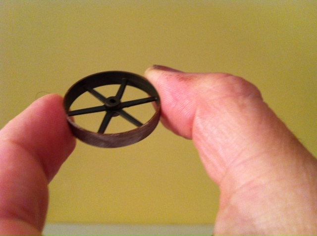
Any thoughts on all this welcome. Here's a picture of one of the flywheels unfinished:
It would be quite nerdly, but probably prudent, to make sure the rotational speed of the line shaft (if that's what the machine is powering) is "correct". There's some discussion on this in the instructions. If the line shaft is to run at a couple hundred RPM for a small machine shop, and the engine is running at a couple hundred RPM, then the flywheel and the drive wheel should be about the same size. This is what is implied in the instructions in the diagram on page 31 of the Machine Shop kit. So one could chose which flywheel to power the line and buff the trim of this one, and leave the other one "dusty" (i.e. no belt). I'm modelling the Sierra RR Machine Shop more or less which in real life is driven by an electric motor which has a small pulley transferring rotational sped to a very large wheel on the line shaft- but I want to "power" the shop by the #318 kit.
Any thoughts on all this welcome. Here's a picture of one of the flywheels unfinished:
Comments
The small wheel on the electric motor leading to a larger wheel would reduce this RPM to the required speed at the driven wheel.
Also from what I believe, the steam engine has one fly wheel and one drive wheel. The fly wheel is a counter balance to the drive wheel and as you say would remain dusty/oxidized/painted. The drive wheel would be polished from its interaction with the belt.
The drive wheel on the engine transfers the power to the driven wheel on the line shaft.
If the steam engines drive wheel is already turning at the correct RPM then the driven wheel would be the same size resulting in a direct RPM transfer.
As you noted, RPM of the driven wheel can be adjusted by varying the two wheel sizes accordingly.
Hopefully an expert can confirm or correct this information if needed.
Karl.A
Out of curiosity, it seems a vintage shop motor might have an RPM of around 1,500 to 1,700. The Sierra RR Machine Shop has a 48" wheel on the drive shaft and an 8" pulley on the motor. This means an RPM of around 250 for the line shaft - about right! As noted this combination lowers the rotational speed from the high RPM of the electric motor.
For the steam engine (ME-#812) kit the driver wheel is noted as 54" so assuming it has a rotational speed of 200 to 300 RPM, the wheel on the line shaft should then be about the same size… makes sense to me…